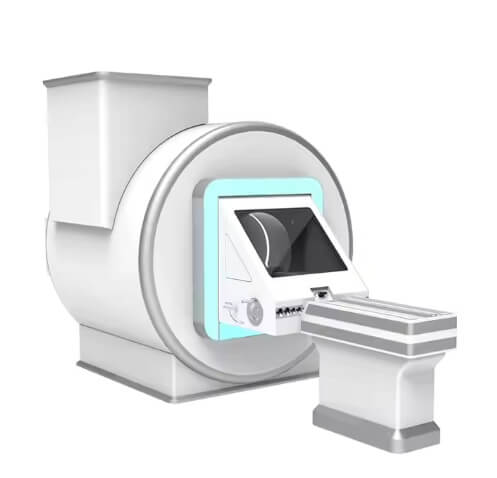
1. Product Overview
MSLCTX13 128 CT system is completely developed by MOOXNO. P-Axial is a patent of the MSLCTX13 128 CT system. It can obtain the thinnest CT images in the 0.3125mm and has obvious advantages in the application of inner ear imaging and pulmonary nodule detection.128-slice dual-energy imaging extended the application of CT dual-energy imaging. MSLCTX13128 CT system provides high-quality images and stable performance which can help hospitals achieve comprehensive accurate diagnosis, redefining the new standards of 128-slice CT imaging.
2. Condition
2.1 Ambient Condition
Parameter Scan room Operation room
Temperature +18℃~+24℃ +10℃~+40℃
Relative humidity 30%~60%(no condensing) 30%~75%(no condensing)
Air pressure 70kPa~106kPa 70kPa~106kPa
2.2 Power Supply
Parameter Condition
Voltage 380VAC±10%;
Frequency 50Hz±1Hz;
Power ≥55KVA;
3. Specifications
S/N Item Specifications
1 Gantry
1.1 Slip Ring Low-voltage slip ring
1.2 Aperture Size 715mm
1.3 Tiltangulation Range ±30°
1.4 The laser Positioning System Provided, provides sagittal, coronal, and internal and external cross-sectional positioning lines
1.5 Scanning Collimation 4x0.625、8x0.625、16x0.625、
32x0.625、64x0.625、64x0.3125
1.6 Sampling Rate 5400 view/ cycle
1.7 Min Scan Time (s/360°) 0.72s
1.8 Max FOV (Field of View) 500mm
1.9 Data Transmission Mode Digital transmission
1.10 Cooling-down Method Air cooling heat dissipation
2 Detector
2.1 Detector Type GOS ceramic solid detector
2.2 Detector Number 880x64
2.3 Detector Row 64
2.4 Image Collection 128 slices (per360°)
2.5 Detector Channel Per Row 880
2.6 Detector Thickness Per Row 0.625mm
2.7 Width of detector 40mm
3 X-ray System
3.1 Focal Point Bifocus
3.2 Focal Spot Size 0.7mmx0.8mm; 1.2mmx1.4mm
3.3 Heat Storage Capacity 3.5 MHu
3.4 Max Anode Cooling Rate 8750W (12250 HU/sec)
3.5 Tube Life 100000-second exposure
3.6 Max Output of Tube Voltage 140kV
*3.7 Min Output of Tube Voltage 60kV
3.8 Output Voltage 60kV, 70kV, 80kV, 100kV, 120kV, 140kV
3.9 Max Output of Tube Current 350mA
3.10 Min Output of Tube Current 10mA
3.11 Max Power 42kW
3.12 Max Continuous Exposure Time 100s
4 Scanner Table
4.1 Horizontal Movement Range 0 ~ 1725mm
4.2 Max Scan Range 1650mm
4.3 Max Horizontal Speed Range 300mm/s
4.4 Repetitive Positioning Accuracy ±0.25mm
4.5 Min Vertical Range 450mm
4.6 Vertical Lift Range 470mm
4.7 Max Load Capacity 205kg
5 Scanning and image reconstruction system
5.1 Scan Mode Tomoscan,Helical Scan, Precision Tomoscan,
Dual Energy Scan(Optional )
5.2 Min Imaging Thickness 0.3125mm
5.3 Recon Matrix 512×512,768×768, 1024×1024
5.4 Max Recon Matrix 1024×1024
5.5 Max Continuous Scan Length 1650mm
5.6 Max Scan Field of View 500mm
5.7 Max Recon Field of View 500mm
5.8 Min Recon Field of View 50mm
5.9 Spatial Resolution 16.6LP/cm@MTF10%
21LP/cm@MTF0%
5.10 Low Density Resolution 3.0mm@0.3%
5.11 CT Value Display Range ±16383
5.12 Display Gray Scale 256, 24bit color
5.13Thin- layer Scanning of Different
Thick Layers Reconstruction Function Provided
5.14
Iterative Reconstruction Provided, P-IR dual-domain iterative de-noising reconstruction technology, real
image, no wax symbol
5.15Posterior Cranial Fossa
Constructed Defect Correction Provided, effective reduction of posterior fossa artifact
5.16Automatic Milliampere Modulation Provided, automatic adjustment of scanning dose according to patient's body
type in X/Y/Z direction
5.17Timing Scan Provided, automatic start of timing
sequence scanning according pre-set time
5.18Tracking Scan Provided, supports manual and automatic
trigger
5.19 Precision Axial Scan The 0.3125mm ultra-thin slice-image can
be obtained by precision axial scanning
5.20
Test-Bolus Scan Provided, test-bolus scan allows for
optimization of time delay by capturing vessels enhancement
5.21
Perfusion Scan Optional, effective and quantificationally reflect the change of tissue blood perfusion, which is able to estimate the
blood supply of the lesion
5.22 CTFLU Scan Optional, support two CTFLU scan mode:
single mode and continuous mode.
5.23
Dual Energy Scan Optional, Dual-energy CT (DECT) utilizes two separate energy sets to examine the different attenuation properties of matter, having a significant advantage over traditional single-energy CT. It can provide
more information for diagnosis
5.23.1 Dual Energy Scan Mode High and Low Voltage Alternation
5.23.2 Low-Dose Dual Energy Scan Support
5.24 240°Organ Protection Scan Mode Although conventional low-dose CT scans can reduce the radiation dose received by patients during the examination,it ignores the different characteristics of different organs' sensitivity to radiation in the human body. In the process of organ protection scanning, the radiation dose of the eyeball, thyroid, mammary gland and other
radiation-sensitive organs on the respectable side of the human body was reduced, and the imaging was carried out
with the data of 240°
5.25 3D Volume-Tomographic Imaging Stepping tomography with certain overlap is used to form continuous volume scan data, which is combined with the axial reconstruction algorithm for image reconstruction, and weighted interpolation fusion was performed for the overlapping images. It can be used in 3D reconstruction to eliminate the step artifacts in conventional 3D reconstruction and the windmill artifacts in the spiral reconstruction
5.26 Precision 3D
Volume-Tomographic Imaging Stepping tomography with certain overlap is used to form continuous volume scan data, which is combined with the axial reconstruction algorithm for image reconstruction, and weighted interpolation fusion was performed for the overlapping images. It can be used in 3D reconstruction to eliminate the step artifacts in conventional 3D reconstruction and the windmill artifacts in
the spiral reconstruction
5.27
Precise Reconstruction Function Make full advantage of the data collected by the detector to reconstruct more and thinner image quantity and provide more
image information
6 Mainframe Computer System
6.1 Console Configuration Single console of original main engine
6.2 Display Specifications 1 set,23.8-inch color flat panel
high-resolution display, display matrix 1920 x 1080
6.3 Main CPU Operand 64 bits
6.4 Main CPU Frame Size 3.5GHz
6.5 Number of Main CPUs 4 cores
6.6 Host Memory 32GB
6.7 Total Volume of Raw Data Hard
Disk 1TB
6.8 Total Volume of Image Hard Disk 1TB
6.9 Mainframe Task Parallel Processing Function Parallel processing of tasks such as scanning, reconstruction, display, image transmission, post-processing,
photography, printing, etc.
6.10 Standard DICOM3.0 Interface Possess
|
7 |
Clinical Application Software and Feature |
|
|
7.1 |
Image Viewer |
Provided, supports plain 2D image browsing |
|
7.2 |
DICOM Viewer |
Provided, supports loading DICOM data in external storage Device |
|
7.3 |
Archives Management |
Provided, classification of patient information according to different conditions |
|
7.4 |
Image Post-processing Function |
Provided, 2D, 3D post-processing |
|
7.5 |
Multiplanar Reconstruction (MPR) |
Provided, provide sagittal, coronal, oblique, curved surface reconstruction |
|
7.6 |
Three-dimensional Reconstruction |
Provided, three-dimensional reconstruction with thin-layer data |
|
7.6.1 |
Volume Reconstruction(VR) |
Provided, supporting volume reconstruction |
|
7.6.2 |
Max Intensity Projection(MIP) |
Provided, support the maximum density projection function |
|
7.6.3 |
Average Density Projection(AIP) |
Provided, support the average density projection function |
|
7.6.4 |
Min Density Projection(Min IP) |
Provided, support the Min Density Projection function |
|
7.6.5 |
Surface 3D Reconstruction (SSD) |
Provided, support the Surface 3D Reconstruction function |
|
7.7 |
Image Format Conversion Function |
Provided, all images can be converted to JPEG, BMP, PNG, DICOM derivative, DICOM screenshot file |
|
7.8 |
Lung Texture Enhancement Software |
Including motion artifact, volume artifact correction software |
|
7.9 |
Automatic Analysis Software for Time Density Curve of Multiple Regions of Interest |
Provided |
|
7.10 |
Spiral scan noise reduction |
Provided |
|
|
software |
|
|
7.11 |
Motion Artifact Correction Software |
Provided |
|
7.12 |
Stripe Artifact Removal Software |
Provided |
|
7.13 |
Respiration Control Graphic Prompt |
Provided |
|
7.14 |
Intelligent Voice System and Two-way Voice Transmission |
Provided |
|
7.15 |
CTA Scan Technique |
Provided |
|
7.16 |
CTU Scan Technique |
Provided |
|
7.17 |
Three-phase Liver Scan Technique |
Provided |
|
7.18 |
Contrast Agent Tracking Automatic Scan Trigger Function |
Provided |
|
7.19 |
AI Scanner Table Removal |
Provided |
|
7.20 |
AI Bone Removal |
Provided |
|
7.21 |
Film Printing |
Provided, printing an image into a film |
|
7.22 |
Peak Analysis |
Provided, after processing the images scanned with the test bolus protocol, the time curve of contrast agent concentration change was obtained |
|
7.23 |
Vascular Analysis Function |
Provided by workstation |
|
*7.24 |
Dual Energy Analysis |
Optional, more information can be obtained by analyzing the data scanned by the energy spectrum function |
|
*7.24.1 |
101-level keV Single-Energy Images |
Optional, the single energy image of the energy level range 40~140keV can be obtained, the low energy region image can improve the contrast noise ratio, and the high energy level can reduce the Harden artifact of the wire beam |
|
*7.24.2 |
80-140kV Mixed Energy Images |
Optional, available to obtain conventional mixed-energy CT images of the scanned location |
|
*7.24.3 |
Material Density Analysis |
Optional, material density images can be reconstructed to provide qualitative and quantitative information on tissue composition and contrast media distribution, and material separation and density analysis can be achieved |
|
*7.24.4 |
Effective Atomic Number Analysis |
Optional, the effective atomic numbers of compounds (such as water) and mixtures (such as muscles or bones) are |
|
|||||||||||||||||||||||||||||||||||||||||||||||||||||||||


